Writer: Andrew MartinRelease Time: 2026-11-04 06:51Browse: 10

A medical imaging display is the screen that presents the image a system captures and gives the operator access to its controls. For equipment manufacturers, choosing one is rarely a matter of matching a screen size to an enclosure. Resolution, brightness, viewing angle, interface, touch and mechanical dimensions all constrain the final design — and in imaging equipment, a display that is slightly wrong shows up as a diagnostic limitation rather than a cosmetic flaw.
This guide covers how displays are used in ultrasound, X-ray and endoscopy systems, what to check when specifying one, and where the common assumptions go wrong.
Contents
A display in an imaging system plays one of three roles: the primary image display, the operating interface, or a secondary information panel. Which role it plays determines almost everything about the specification.
Ultrasound images change continuously as the probe moves and settings are adjusted. Resolution, brightness and viewing angle all matter here, but responsiveness matters just as much — a panel that lags or shows motion blur makes it harder to read a live image.
Touch is increasingly common because the operator is working one-handed with the probe. On portable and handheld units, size and power consumption then become the deciding constraints.
Requirements split by what the screen is for. A display built into the equipment for operation and preview leans toward resolution, brightness, signal compatibility and ease of use. A monitor used for diagnostic reading is a different product category, judged on image detail, grayscale response, luminance uniformity and calibration.
A standard embedded LCD module should not be treated as a diagnostic radiology display without the necessary system-level evaluation. That distinction matters commercially as well as technically, because it decides which supplier you are actually buying from.
Color reproduction carries diagnostic weight in endoscopy, because the displayed image contains visual information about tissue. The chain to verify runs from camera output through the image processor to the display input; a mismatch anywhere in that chain shows up as color that does not match what the clinician expects.
Touch interfaces, where used, should be designed around the actual procedure workflow — often gloved, often during a procedure where the operator's attention is elsewhere.
Portable and handheld imaging devices trade everything for space and battery. What tends to matter, in rough order:
The table below summarizes typical ranges, not specifications. Treat it as a starting point for the conversation with your display supplier rather than a purchasing document.
Handheld and portable devices usually settle in the 5–7 inch range. Larger ultrasound consoles and control panels run 10–15 inches and up.
Beyond the diagonal, two things get missed. The first is aspect ratio, which affects how the system's UI is laid out. The second is the native resolution of the main board or image processor. Matching the display to that native resolution avoids scaling, which softens exactly the detail imaging equipment is bought for.
Brightness determines whether an image is readable under the lighting the device will actually meet. Contrast matters most on images that contain both bright and dark regions at once.
Higher brightness is not automatically better. It costs power, shortens backlight life, and can wash out low-contrast detail if the panel is not designed for it. Set a target from the installation environment, viewing distance and system requirements.
Operators rarely sit square to the screen. This is why IPS TFT LCD is common in imaging equipment, though the label alone does not guarantee anything. Check the specified viewing angles in all four directions rather than judging by the panel category.
Endoscopy systems depend on color accuracy; diagnostic radiology depends on grayscale.
Two things a component datasheet will not tell you. First, standard module specifications do not establish DICOM compliance. Second, a datasheet contrast ratio says nothing about how evenly luminance is distributed across the panel, which is the figure that shows up as banding on a uniform gray field.
Interface compatibility is one of the first things to confirm, and one of the easiest to get wrong late.
A display with the right resolution can still be unusable if its interface, data rate, timing or connector pinout does not match the host system. Check the electrical requirements at the same time as the protocol.
Capacitive touch, in-cell touch, or no touch at all — the choice follows the workflow, not the trend.
Where touch is used, the details that decide whether it works in practice are cover glass thickness, controller compatibility, surface treatment, sensitivity through gloves, and resistance to the cleaning agents used on the enclosure. After integration, ground, electrical noise and the cover lens design all need testing; a touch panel that tests perfectly on a bench can behave differently inside a metal housing.
Confirm operating and storage temperature ranges, module thickness, outline dimensions, connector position and mounting features.
Then ask the question that is easy to skip: can this exact configuration still be sourced three years from now? A display that performs well in the prototype should remain practical to buy through the product lifecycle, and that is a supply question rather than a datasheet question.
Only if the display is used for diagnostic interpretation — and even then, compliance belongs to the whole system, not to the panel.
DICOM Part 14 (PS3.14) defines the Grayscale Standard Display Function, a relationship between digital input values and displayed luminance intended to make perceived contrast consistent. A display module purchased from a component supplier is not DICOM-compliant on its own, regardless of what its datasheet says about contrast or bit depth.
Compliance is established through calibration and verification of the assembled display system, including the graphics pipeline, backlight stability and ambient light conditions. In practice this means two different procurement conversations:
Being clear about which conversation you are in avoids both over-specifying a control panel and under-specifying a reading station.
TFT LCD is the default for imaging equipment. It covers a wider range of sizes, resolutions and interfaces than any alternative, and the supply base is deeper. For ultrasound consoles, control panels, portable imaging devices and patient monitors, a well-chosen IPS TFT module solves most of the problem.
OLED earns its place where the design values contrast and compactness: self-emissive pixels, true blacks, a thin profile. What it asks in return is a closer look at brightness headroom, operating life, image retention, thermal behavior and long-term supply. An OLED module is not automatically suitable for diagnostic image interpretation simply because it offers high contrast; the same system-level evaluation applies.
We compared the two technologies for medical use in more detail in LCD versus OLED for medical devices.
Two examples from our medical display range, both available as standard modules with customization options.
ET070WU13-TT is a 7 inch IPS panel at 1200×1920 with MIPI input, 1500 cd/m² typical brightness and 85/85/85/85 viewing angles. The high brightness and portrait format suit compact handheld imaging and diagnostic devices where the screen has to stay readable outside a dim room, and thickness and touch integration both matter. View ET070WU13-TT
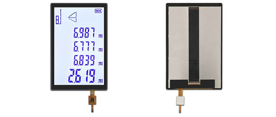
ET121WX05-TT is a 12.1 inch 1280×800 panel on LVDS with 750 cd/m² and capacitive touch, at 85/85/85/85 viewing angles. It suits equipment panels and portable systems that need readability in brighter clinical environments and enough area for a full imaging interface. View ET121WX05-TT
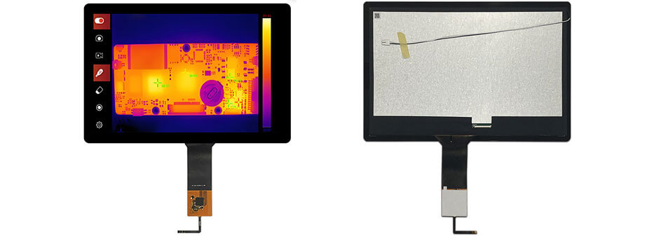
Both are embedded display modules. Final suitability depends on the equipment design, the image-processing requirements and the validation results, and neither should be regarded as a certified diagnostic monitor.
Our full range of TFT LCD display modules covers sizes from small handheld formats up to large-format panels, with IPS, high-brightness and wide-temperature options. For how these modules fit into medical equipment more broadly, see our guide to what a healthcare display is, and for the monitoring side, our notes on patient monitor displays.
Before requesting samples or starting integration, it helps to have these answers ready.
For diagnostic applications, also define the image quality evaluation and calibration process early. It affects which supplier you can work with, because not every module supplier can support a calibration workflow downstream.
Where a standard module does not fit, customization usually covers LCD size and resolution, brightness and viewing angle, interface (MIPI, LVDS and others), capacitive or in-cell touch, module outline and FPC layout, and operating temperature range.
If you are working on an imaging device and want to talk through the display requirements, get in touch with our engineering team. Dimensions, a target specification or an existing part number is enough to start.
TFT LCD is the most widely used, mainly because it covers the widest range of sizes, resolutions, interfaces and brightness levels. OLED appears in designs where contrast or a thin profile matters, subject to evaluation of lifetime and supply.
There is no single answer. It depends on screen size, the imaging system's output, viewing distance and the UI design. The practical rule is to support the native output of the imaging chain rather than upscaling a lower-resolution source.
Yes, for control, preview and secondary information functions. A screen used for primary diagnostic interpretation is a different category with additional requirements, and should be evaluated at the complete display system level.
Only displays used for diagnostic interpretation. DICOM Part 14 compliance is established by calibrating and verifying the assembled display system, not by the panel module alone.
Not necessarily. Touch follows the operating workflow: common on ultrasound and portable devices, less so on endoscopy towers and reading stations.
Size, resolution, interface, brightness target, touch requirements, mechanical dimensions and operating temperature. Drawings or a reference part number help considerably.
Yes. We supply TFT LCD, IPS, high-brightness and touch-integrated modules for healthcare equipment, with standard and customized configurations.


