Writer: Andrew MartinRelease Time: 2026-11-16 08:13Browse: 5

The cluster is the one screen in the vehicle nobody chooses to look at. Drivers glance at it for half a second at a time, at a fixed distance, through a hood, behind a cover glass, at noon and at two in the morning. That single fact reorders every specification: brightness matters less than reflection control, resolution matters less than the size of the smallest digit, and touch — which every other screen in the car now has — is usually the wrong answer here.
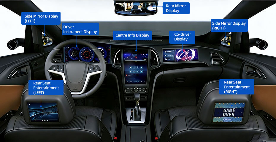
This article covers what an instrument cluster display actually does, why TFT LCD replaced mechanical gauges, the seven specifications that decide whether a module can serve in a cluster, the optical stack between the panel and the driver's eye, and four real modules from 6.2 to 12.3 inch with their numbers and their limits. For the wider picture across the whole vehicle, read Automotive Display: Types, Applications and Key Requirements and How to Choose Automotive Display.
Contents
An instrument cluster display presents driving information to the driver: speed, engine RPM, fuel or battery level, gear position, warning indicators, and in electric vehicles, energy flow and remaining range. It sits behind the steering wheel or across the driver's side of the dash, and unlike every other display in the vehicle, its content is safety-relevant by definition.
What the module itself does is narrower than what the cluster does. The display module provides pixels and backlight. The vehicle's control units decide what information arrives; the SoC and graphics software decide how it is drawn; the optical stack decides whether the driver can actually read it. A cluster project that treats the panel as the whole system will discover the other three parts late and expensively.
Typical content on a digital cluster:
Notice what is not on that list: maps, video, menus. A cluster shows a small vocabulary of elements, repeated in fixed positions, for the life of the vehicle. That is why the specification work concentrates on legibility and stability rather than on raw pixel count.

Mechanical gauges still exist, but the trend is one-way. A TFT LCD lets the same hardware show different layouts through software — a sport mode with a central tachometer, an eco mode with a consumption history, an EV layout with a battery arc. For platforms that sell in several trim levels, one module with several UIs beats three gauge designs with three tooling sets.
Three properties decide the technology choice for this position:
Stability with static content. A cluster shows the same speedometer ring, the same label positions, often the same brightness, for years. LCD backlights age uniformly; OLED pixels age by how hard each one is driven, which is exactly how a static UI drives them. Burn-in risk is why OLED appears in premium centre displays far more often than in clusters.
OLED can offer deep blacks, high contrast and fast pixel response, making it an option for digital instrument cluster applications. However, prolonged display of static elements, such as speed indicators, warning icons and fixed dashboard graphics, may increase the risk of image retention or burn-in over time. This should be considered when evaluating OLED for instrument cluster designs.
OLED can also be considered for instrument cluster applications, depending on the required brightness, lifetime, static-content exposure, operating environment and overall system design.
Brightness headroom that survives the stack. A cluster panel needs enough brightness to lose 20-30% to the cover glass, bonding and hood shading and still hold its contrast target. LED backlights give that headroom in a form that scales predictably from 700 to 1600 nits.
A temperature envelope that covers a parked car. Wide-temperature TFT modules rated -30 to 85 °C are commodity parts now. Cold-start behaviour — the seconds after ignition at -30 °C when the liquid crystal is sluggish — is the part to test, because no datasheet line captures it.
Very small segments of the market still use PMOLED or segment LCDs for indicator-only clusters on low-cost vehicles and two-wheelers. Those are status readouts, not displays, and they end the moment the UI needs graphics.
Everything else is negotiable. Fail one of these seven and the module cannot serve in a cluster, whatever the rest of the datasheet says.
The question is not "is 1024 × 600 enough" but "how big is the smallest character at 600 mm". A 7-inch panel at 1024 × 600 gives about 170 ppi — a 6 mm digit is drawn from roughly 40 pixels of height, which is comfortable. The same resolution across a 10.3-inch wide strip gives a larger digit from the same pixel count, at lower ppi. Cluster layouts tolerate moderate ppi well because their content is large and fixed; infotainment tolerates it badly because its content is dense.
Night driving needs a dim panel — a cluster at full brightness in a dark cabin is glare. Daylight needs the opposite. What matters is the ratio between minimum and maximum luminance, and whether the backlight supports PWM dimming smoothly across it. A module that dims from 1600 nits down to a few cd/m² without visible stepping is worth more than a brighter one that cannot go dim cleanly.
The driver's eye moves with seat adjustment, but the range is narrow — which is why clusters work with panels that would fail as passenger screens. What matters is contrast and colour stability across that specific cone, not the datasheet's symmetric maximum. Check L/R/U/D figures against the actual mounting angle: a cluster mounted above the steering column views the panel from below, and a panel with an asymmetric vertical viewing angle will shift there.
Warning indicators have defined colours (red, amber, yellow, blue, green) and must stay recognisable through the cover glass. Contrast decides whether the dark background of the cluster reads as black or as grey — and a grey background at night hides every low-brightness element on it. Evaluate with the real UI: fine ticks, thin arcs and small coloured icons behave differently from full-screen test patterns.
Confirm operating and storage ranges, then ask what happens at the ends. At -30 °C, LCD response time multiplies several-fold; the first seconds of a cold start can look smeared until the panel warms. At 85 °C after a sun-soaked park, brightness and contrast drift. A wide-temperature rating is the entry ticket; cold-start behaviour is the test that finds the real differences between panels.
Active area, viewing area and outline are three different numbers, and only the outline one is mechanical. A 12.3-inch 1920 × 720 module with a 292 × 109 mm active area sits in a 310 × 128 mm outline — roughly 9 mm of bezel left and right. Also check FPC exit direction and connector clearance against the steering column and the cluster housing ribs; the cable path kills more cluster designs than the panel size does.
LVDS is commonly used in larger automotive display modules because of its suitability for high-speed video transmission. MIPI and RGB interfaces are also used in certain designs, depending on the host processor and system architecture. MIPI appears on compact vertical modules paired with mobile-class SoCs. RGB survives on small panels with short flex runs. Beyond the interface, confirm backlight drive location (on the module or on your board), connector and pin assignment, supply voltage, and — for a safety-relevant display — startup and wake behaviour, because a cluster that is still blank two seconds after ignition is a warranty event, not a spec footnote.
The most common cluster mistake is specifying the LCD and treating everything in front of it as packaging. The driver sees the complete stack: panel, polariser, optional touch sensor, cover lens, coatings, and the hood geometry around all of it. Every layer adds reflection; the hood determines how much sunlight reaches the stack in the first place.
What each option actually buys:
Anti-glare treatment. Scatters specular reflection into a diffuse haze. Cheap, effective at killing mirror-like hot spots, at the cost of slightly reduced perceived contrast on fine text. The default choice for hooded clusters.
Anti-reflective coating. Cancels reflection at the surface rather than scattering it. Better contrast gain, more expensive, and more fragile — a consideration where the cluster is cleaned or touched.
Optical bonding. Removes the air gap between panel and cover lens, eliminating two internal reflections at once. Typically recovers 8-15% of contrast in bright conditions. Decide before the mechanical design freezes, because it changes stack height, tolerances and rework strategy — it is not an upgrade bolted on at the end.
Touch. Rarely needed on a cluster, and a finger on the cluster glass is both a distraction and a smudge in the driver's line of sight. When the platform genuinely needs one glass across cluster and centre display, in-cell touch keeps the stack thin and the surface clean; a bonded add-on PCAP adds two reflective layers that the brightness budget then has to buy back.
Whichever combination is chosen, evaluate it installed — real hood, real glass, real sun. A panel number measured bare in a dark room does not survive translation into an assembly.
A small display beside or within a partially mechanical cluster: gear indicator, odometer, warning block. 4 to 7 inch, moderate resolution, simple interface, cost-driven. The display risks are mechanical fit and dimming behaviour, not graphics performance. Two-wheelers and entry cars live here, and portrait or round formats are common.
One wide panel carries everything: 10.3 to 12.3 inch, wide aspect ratios (8:3 formats have effectively become the cluster standard), graphics-grade SoC behind them. Here the specifications that matter are brightness uniformity across a long panel, viewing-angle consistency along its width, and cold-start response. This is also where "the cluster and the centre display are one continuous glass" designs live, which drags touch and bonding decisions into a cluster that would not otherwise need them.
Same panel class as a full digital cluster, different content: state of charge, range estimation, power flow, regenerative level. The panel does not make any of those numbers more accurate — they come from the vehicle's BMS. What the display adds is the duty of showing them legibly at all times, including the consumption graphs and colour-coded power arcs that make EV UIs denser than ICE ones. Check colour performance against that UI, not against a generic test chart.
For legibility, the industry reference is ISO 15008:2017 — Road vehicles — Ergonomic aspects of transport information and control systems — Specifications and test procedures for in-vehicle visual presentation. It specifies minimum image-quality and legibility requirements for displays presenting dynamic information to a passenger-car driver in motion: character legibility, colour recognition, and the measurement procedures to verify them. It is deliberately technology-independent — it does not prescribe LCD, OLED or anything else.
Two boundaries of the standard are worth knowing before you cite it. First, scope: it excludes pictorial content such as camera images and maps, superimposed information such as HUD, and quasi-static text — which means it covers the cluster's core job (numbers, symbols, tell-tales) precisely, and infotainment mostly not at all. Second, status: the 2017 edition is currently under revision, so confirm which edition your programme references before writing it into a specification.
And the boundary that matters most commercially: ISO 15008 addresses legibility of the visual presentation, not environmental, electrical or reliability qualification of the display module. A supplier who provides a panel with published legibility-relevant specifications has supplied a component. Compliance of the finished cluster rests on the vehicle manufacturer's validation — which is exactly how it should be, because the hood, the glass and the software are not the supplier's to test.
The ten-line brief below gets a useful quotation in a day. The five items after it get the right samples instead of plausible ones.
| Item | Information to confirm |
|---|---|
| Cluster layout | Compact / hybrid, full digital, or EV instrument panel |
| Display size | Target diagonal and available installation space |
| Resolution | Pixel dimensions, and the smallest character it must render |
| Brightness and dimming | Daylight target and minimum night luminance |
| Viewing angle | Driver eye position and panel mounting angle |
| Technology | TFT LCD, IPS TFT LCD, or open to recommendation |
| Interface | LVDS, MIPI, RGB — and the host SoC it must match |
| Mechanical design | Outline, thickness, mounting, FPC exit direction and cable path |
| Environment | Operating and storage temperature; cold-start requirement if defined |
| Programme stage | Prototype, engineering validation or mass production; volumes |
Beyond the table: a mechanical drawing or an existing part number, the cover-lens concept if one exists, and whether the UI is fixed or software-switchable. If an existing module is being replaced, its part number and drawing shortlist the candidates faster than any specification form.
Five display modules covering different cluster sizes and application requirements are listed below. Their specifications illustrate how resolution, brightness, interface and temperature ratings vary across different designs. The point is not to pick one from the table — it is to see how differently the same numbers get balanced at each size.
| Part No. | Size | Resolution | Interface | Brightness | Outline (mm) | Temp / touch |
|---|---|---|---|---|---|---|
| ET062BA06-TT | 6.2" | 480 × 1280 | MIPI | 1200 | 62 × 163 | -30~85 / in-cell |
| ET070WS07-KT | 7.0" | 1024 × 600 | LVDS | 1600 | 182 × 117.6 | -30~85 / no |
| ET103BA01-HL | 10.3" | 1280 × 480 | LVDS | 800 | 258.6 × 109.8 | -40~85 / no |
| ET123BA05-T | 12.3" | 1920 × 720 | LVDS | 1200 | 310 × 128 | -30~80 / no |
| ET123BA01-AP | 12.3" | 1920 × 720 | LVDS | 1200 | 302.06 × 125.46 | -30~85 / in-cell |
480 × 1280 in a 62 × 163 mm portrait outline is the shape a motorcycle or scooter cluster needs: narrow enough to sit in a handlebar-mounted housing, tall enough for a speed arc, a battery bar and a gear indicator.

The limit is the 480-pixel width: roughly 26 characters of 5 × 7 font per line. That is a readout, not a menu system. If the UI needs a map preview or dense text, this shape is wrong before any other number is discussed.
1600 nits at 7 inch is the highest figure in this table, and it exists for cabs with more glass than roof: trucks, agricultural machines, construction equipment, where the cluster fights daylight all shift.

Two honest limits: 1024 × 600 is coarse for street-level map content, and 1600 nits means the backlight does real work — plan the current budget and the heat path at full brightness, and plan the dimming curve, because this panel must also go dim enough for night driving.
1280 × 480 at 10.3 inch is a 243.84 × 91.44 mm band — a 40 mm tall strip across the dash, which is the geometry a growing share of cluster designs actually use.

The trade is brightness for cold rating and power: this is not the panel for a sun-exposed, hoodless installation. It is the right one for a shaded dash that must wake up reliably at -40 °C, which is a cluster requirement the brighter panels above do not carry.
1920 × 720 at 12.3 inch, 8:3, IPS with 88/88/88/88 viewing angles, 6 mm maximum depth. This is the geometry that defines a full digital cluster: wide enough for speed, tell-tales and driver-assist status in one band, shallow enough to sit behind a conventional cluster hood.
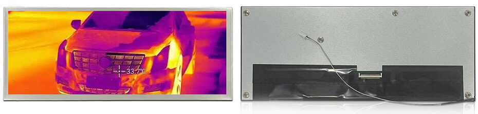
When the platform does need touch on the cluster glass — usually because cluster and centre display share one continuous cover lens — the same panel family exists with in-cell touch: ET123BA01-AP, same resolution and brightness, slightly different outline (302.06 × 125.46 mm), rated to 85 °C. Same class of part, different mechanical — which is exactly why the outline drawing, not the diagonal, is the number to design from.
More sizes exist on the shelf — the automotive range covers 5 to 32 inch and beyond, including 8, 12.8 and 17 inch panels. Browse the automotive display selection or the full LCD display range.
TFT LCD, usually IPS-mode, dominates. It holds a wide temperature envelope, dims cleanly from daylight to night levels, and — decisively for a screen that shows the same static layout for years — has no image-retention risk. OLED appears in premium centre displays far more often than in clusters, precisely because static content accelerates differential aging.
No standard exists. Compact and two-wheeler clusters run 4 to 7 inch, full digital clusters 10.3 to 12.3 inch in wide 8:3 formats. The dashboard opening and viewing distance decide it, not the market: build the mechanical model from the outline drawing of the exact part number before committing.
In most cases, effectively yes. A cluster is viewed from a fixed but slightly varying eye position, including from below when mounted above the steering column, and IPS-type modes keep contrast and colour stable there. Check the L/R/U/D figures against your actual mounting angle rather than trusting the "IPS" label alone.
No. The driver sees the stack — panel, touch layer if present, cover lens, coatings and hood geometry — and every layer adds reflection. A 1000-nit panel behind untreated glossy glass can read worse than a 700-nit panel behind a bonded anti-glare one. Specify the brightness target for the assembly and test it installed.
Often yes, with a qualification plan. The -30 to 85 °C rating says the liquid crystal survives the range; it says nothing about cold-start behaviour, vibration, thermal shock or long-term backlight drift. Those are settled by the vehicle programme's test plan — agreed before samples, not after.
Usually no: the cluster is a glance instrument, and a finger on it is a distraction in the driver's line of sight. Touch enters only when the cluster shares one continuous glass with a centre display. In that case, in-cell touch keeps the stack thin; a bonded add-on sensor adds reflective layers that the brightness budget must then recover.
Yes, within limits: FPC length and exit direction, connector position, backlight brightness and its driver, cover-lens shape, thickness and print, optical bonding, and driver-board configuration. What cannot change: the glass itself, pixel pitch and aspect ratio. A 1280 × 480 band will not become 1920 × 720, and a TN panel will not become IPS. Confirm feasibility against the specific panel before the mechanical design freezes.
Youritech provides TFT LCD display modules for automotive instrument cluster and other in-vehicle display applications. Whether your project requires a compact display or a wide-screen dashboard module, our team can help evaluate suitable display options based on your technical requirements.
To help us understand your project, please share the target display size, resolution, brightness, interface, operating temperature range and mechanical dimensions. We can discuss suitable display modules and customization possibilities according to your application.
Contact Youritech to Discuss Your Automotive Display Project.