Writer: Andrew MartinRelease Time: 2026-11-13 06:24Browse: 2

A 12.1-inch panel arrives for evaluation. It fits the cut-out, the LVDS cable reaches, the image looks fine on the bench — and then the firmware team points out that the main board only outputs MIPI. Two weeks and one bridge board later, the display works, the BOM has a new line item, and nobody is sure who approved the original choice.
Most medical display module problems are not image problems. They are interface, mechanical and lifecycle problems that were visible on page two of the datasheet before the sample was ordered.
This guide covers the eight specifications that decide whether a module fits a medical device, in the order worth checking them, plus the standards questions that come up in every diagnostic imaging project.
Contents
Size decides how much information fits on the screen; resolution decides how much detail survives inside that area. They are chosen together with the enclosure and the viewing distance, which is why starting from a preferred diagonal usually ends in a redesign.
A patient monitor needs six waveforms and large numerals — screen area runs out before pixel count does. A handheld ultrasound needs to resolve small structures — pixel density runs out before area does. Those two sentences send you to different parts of a catalogue.
Rough bands that hold in practice: 3.5 to 5 inches for handheld instruments, 8 to 12.1 inches for patient monitors and control panels, 15 to 21 inches for imaging review and surgical displays. A 4:3 panel is still common on legacy instruments because the mechanical envelope and the UI were designed around it; changing to 16:9 means rebuilding both.
Take the diagonal in pixels, divide by the diagonal in inches. On a 12.1-inch panel:
Same glass size, three times the density. For menus and numbers, 106 ppi is completely adequate. For a 1 mm structure in an ultrasound image, it is not, and no amount of interface tuning fixes that.
Two modules can share an outline dimension and place the active area differently inside it. If the drawing shows the active area 2 mm off-centre, the bezel will be uneven and no firmware change helps. Ask for the mechanical drawing with the active area positioned relative to the outline, not a standalone active-area figure.
Higher resolution costs bandwidth, memory, power and often a different interface. If the source is a 1280×800 UI, a 1920×1200 panel adds scaling artefacts and cost without adding information. Match the native output of the processor.
Brightness is a lighting decision before it is a display decision. Pick the number from the worst room the device will sit in, then check the power figure at that brightness rather than at typical.
300–500 cd/m² covers a ward, an examination room and a control cabinet. 700–1000 cd/m² handles a bed beside a window, an ambulance or a device used outdoors in shade. Above 1000 cd/m² is direct-sunlight territory, and it comes with a thermal design, a shorter backlight life and a power bill.
Surface treatment moves the effective number more than people expect. A matte, anti-glare front can make 500 cd/m² more legible than a glossy 700 cd/m² panel reflecting a ceiling light.
A 1000:1 figure is measured in a dark room with a test pattern. In a lit ward, the black level is set by reflected ambient light, not by the panel, and the effective contrast collapses. If the device is used in a bright room, the front surface treatment and the black-level uniformity matter more than the datasheet contrast ratio.
For waveform displays, what actually matters is that thin lines stay distinguishable against a dark background at the real ambient level. Test that on the bench with the room lights on, not with a checkerboard in a dark room.
Backlight current scales roughly with brightness and area, so the display is usually the second-largest load after the processor and sometimes the first. Backlight lifetime is quoted to half brightness — typically 20,000 to 50,000 hours — and a device that runs its backlight at maximum all day will reach the low end.
Viewing angle matters wherever a second person reads the screen or the operator works off-axis. Colour and grayscale matter much less than the marketing suggests — until the device is used to interpret an image, at which point they matter completely.
Datasheets give the four directions as L/R/U/D at a stated contrast ratio, usually 10:1. 89/89/89/89 is a strong, symmetric result; 80/80/80/80 is common on high-brightness panels and fine in practice. What the numbers do not describe is colour shift at that angle, which is why an IPS panel and a TN panel with similar nominal angles look so different off-axis.
Evaluate with your own UI on the panel, tilted 30–40° in the actual enclosure. A cover lens with printed borders and an air gap changes the result compared with a bare module on a bench.
Endoscopic video and dermatology imaging want believable colour. Most other medical devices want consistency: the same alarm red and the same waveform green on every unit in a department, so a nurse trained on one device reads the next one the same way. Ask about batch-to-batch colour tolerance rather than gamut percentage if consistency is the actual requirement.
The DICOM Grayscale Standard Display Function (GSDF, PS3.14) defines a standard relationship between digital image values and displayed luminance, plus methods for measuring a display system against it.
What it does not do is certify a panel. A bare LCD module cannot be "DICOM compliant" in any meaningful sense: GSDF is a property of a calibrated display system, measured after installation, with a defined luminance range, ambient conditions and quality-assurance process. A module that shows a grayscale step wedge is not a diagnostic display.
The same distinction appears on the regulatory side. The FDA guidance on display devices for diagnostic radiology addresses devices classified for that intended use; it is not a checklist for every LCD inside a medical device. Apply it where the intended use matches, and do not stretch it over a module in a pump or a monitor.
For a device that shows numbers, waveforms and menus, none of this section applies. It becomes relevant the moment a clinician is expected to make a judgement from the image.
Interface is the most common reason a technically suitable module fails integration. Match the module to the board, not the other way round: a bridge chip adds a rail, a failure mode, an EMC question and a month.
A 1920×1080 panel at 60 Hz with 24-bit colour needs roughly 3 Gbit/s of payload. That is comfortable on four MIPI lanes or dual-channel LVDS, and impossible on SPI. Work the number out before the shortlist, not after the first sample fails to lock.
Two modules described as "40-pin MIPI" can differ in pin order, FPC contact side, backlight connector and mounting ears. Ask for the pin definition and the connector part number, and compare them with your board schematic. This single check prevents most first-sample failures.
Panels typically need 3.3 V logic, an analogue rail around 10 V and a backlight string that may run from 12 V or from a dedicated driver. Check the sequencing requirement — some panels need VDD before the signal, some the reverse — and whether the backlight driver is on the module or on your board. "Backlight driver not included" is a line item that appears on page two.
On a monitor or an analyser, touch is usually the primary input. That makes the touch layer and the cover lens part of the display assembly, not an accessory added at the end.
Add-on capacitive (GFF or GG) is the flexible option: the touch panel is a separate part, sourced and bonded independently, and the display module stays a standard catalogue item. In-cell integrates the sensor into the panel — thinner, often brighter, and locked to that panel's controller.
Neither is automatically right. A transport monitor operated with gloves, a device used with wet hands, and a workflow where a rotary knob is simply faster all argue for hardware controls. Test gloved operation early: an in-cell layer tuned for bare fingers may need different firmware settings or a thinner cover.
Cover glass is typically 0.7 mm or 1.1 mm. Thicker glass survives impact better and costs touch sensitivity and transmission. Air bonding is cheaper; optical bonding removes the internal reflection that makes a screen look grey under a window, and it is close to mandatory for a high-brightness panel used near daylight.
Printing, anti-glare and anti-fingerprint coatings all interact with the cleaning agent. If the device is wiped with alcohol or quaternary ammonium between patients, say so when the drawing is quoted — the ink and the adhesive change with the chemistry, and this cannot be fixed after tooling.
Touch performance in a finished housing is an electrical question. Grounding, the gap between cover and panel, FPC length and nearby switching regulators all shift the result. Build one complete unit and test it with gloves, with wet hands, and with the charger connected.
A module can meet every optical requirement and still not fit. Mechanical review belongs before the enclosure is tooled, not after the first prototype.
Outline dimensions, active area position, module thickness including touch and polariser, FPC length and exit edge, connector position, mounting holes or frame features, and the cover lens dimensions if it is bonded. Confirm the thickness figure includes every layer you are buying; a 4.2 mm module and a 2.3 mm module look the same in a summary table.
-20 to +70 °C covers indoor equipment; -30 to +85 °C appears on wide-temperature panels intended for transport, outdoor or vehicle use. Check what changes at the cold end: response time slows, brightness drops, and a device stored in an unheated vehicle will meet that condition in service. Storage range is normally wider and matters for shipping and warehousing.
Anything that travels — ambulances, home-care visits, carts — should have the mounting method reviewed, not just the panel. A module held by four M5 screws behaves differently from one clipped into a plastic frame with foam tape.
Medical equipment programs run five to seven years, and sometimes twelve. Ask for the product lifecycle status, the notice period for last-time-buy, and how change notifications are handled. A module that reaches end of life in year three turns a validated design into an unplanned re-validation, which is far more expensive than the display itself.
One page of requirements turns the first quotation round into a shortlist. The table below is what a supplier needs to answer properly.
A drawing, the module number being replaced, or a main board interface description shortens this list considerably. "A 12-inch screen for a medical device" is not a requirement; it is the start of four emails.
Two 12.1-inch modules from our range show how far apart two panels of the same size can sit: one is the LVDS workhorse for monitors and control panels, the other is a 6.4-megapixel panel for imaging with the touch layer built in. Both are modules, not finished displays; validation stays with the equipment manufacturer.
Product page: 12.1 inch Wide Temperature TFT LCD 1024×768 LVDS 600 nits
This is the module that fits the largest number of medical projects: 4:3, LVDS single link, no touch, and a temperature range that covers transport and unheated rooms without a special order.

The honest limitation: 106 ppi is fine for waveforms and numerals and not enough for image interpretation. 600 cd/m² is comfortable in a ward and marginal at a window, and the panel has no touch, so a touch project needs the CTP variant rather than this exact part number.
Product page: PPC100HB1-1 12.1 inch 3000×2120 MIPI with In-Cell Touch
Same diagonal, about three times the pixel density, and the touch sensor is inside the panel rather than bonded on top. For a handheld or cart-based imaging device, this is the density class where a 1 mm structure stops looking like a mosaic.
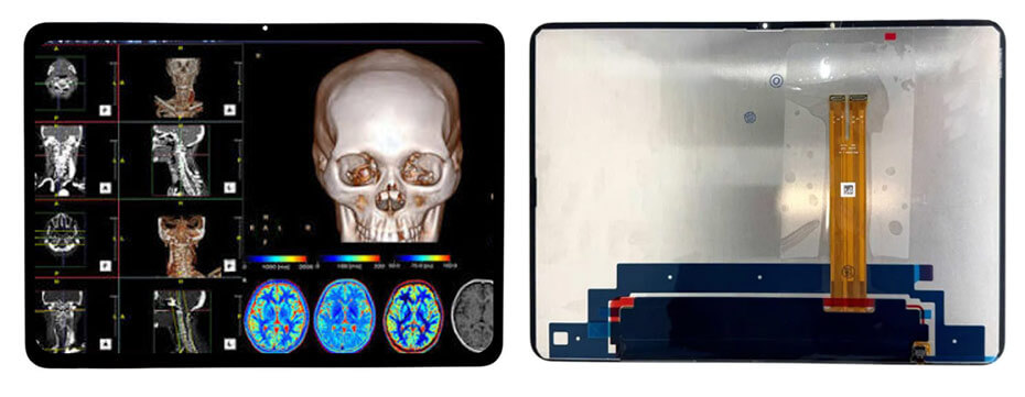
Two things to plan for. The 3000×2120 stream needs a processor that can actually drive it over four MIPI lanes — check the SoC datasheet before assuming it will. And the -20 to +60 °C operating range is narrower than the LVDS module above, which rules it out of vehicle or outdoor use, however good the picture is.
If the project needs a different combination — 15-inch 1024×768, 13.3-inch 1920×1080 eDP, a high-brightness variant, or a bonded cover lens — our TFT LCD module range covers 0.5 to 32 inches with the same selection logic applied.
Custom work usually starts where the catalogue stops fitting: a brightness level between standard steps, a specific FPC exit, a bonded cover lens with printed borders, a wider temperature range, or an interface the standard module does not offer. Requirements we handle regularly:
If the device is handheld or battery powered, the constraints change considerably — our guide to portable medical displays covers thickness, power budget and daylight readability. For image-capture and review devices, the medical imaging display guide goes further into resolution, grayscale and calibration, and the healthcare display overview explains how medical variants differ from standard industrial modules.
Selecting a module for a medical device? Send your size, resolution, interface and touch requirements through our contact page and we will come back with module options, drawings and customization notes.
Interface compatibility, because a mismatch stops the project before image quality is ever judged. After that, size and pixel density decide whether the content is legible, and mechanical dimensions decide whether the module goes into the housing at all.
300 to 500 cd/m² for wards, examination rooms and enclosed panels. Devices used near windows, in ambulances or outdoors generally need 700 to 1000 cd/m² with an anti-glare surface. Every step up costs backlight power and shortens backlight life.
Wherever more than one person reads the screen or the operator works off-axis, yes in practice. IPS holds colour and contrast at 30 to 60° of tilt, where a TN panel washes out. For a panel viewed head-on by one operator, it matters much less.
No, and a bare module cannot be. DICOM GSDF (PS3.14) describes how a calibrated display system should map image values to luminance; conformance is established at system level, after installation, through measurement and quality assurance. Modules are components, not diagnostic displays.
Yes, provided it meets the technical requirements and the finished device is validated as a whole. The module supplies an image; it does not establish regulatory compliance, which is assessed on the complete device by its manufacturer.
Screen size and resolution, interface and lane count, brightness target, touch requirement, outline and thickness limits, FPC exit, operating temperature, expected volume and the project stage. A drawing or the part number being replaced shortens the discussion considerably.
Yes — size, resolution, interface, brightness, touch integration, cover lens, FPC layout and temperature range can be adjusted, and non-standard aspect ratios are possible. Standard and semi-custom options usually shorten the schedule, so they are worth checking first.


