Writer: Andrew MartinRelease Time: 2026-11-16 06:00Browse: 5
 The enclosure tooling is finished. The screen opening is fixed at one size, the flex has to exit on a specific edge, and the main board speaks LVDS. Then somebody finds a module with the right resolution and the wrong everything else. That is usually the moment a custom display project starts — not with a wish list, but with three or four dimensions that a catalogue part does not satisfy.
This article walks through when a medical equipment project actually needs a custom display, what standard, semi-custom and full-custom each change, which parts of the assembly can be modified, and how the work moves from module selection to production.
Contents
Short answer: when at least one hard constraint of the equipment — mechanical, electrical or optical — cannot be met by any module you can order from a product page. One mismatch is enough to start customization. Four mismatches mean the project was probably specified backwards.
These are the four situations we see most often in medical enquiries.
Medical equipment usually locks its front panel early. The opening, the mounting bosses and the depth budget are decided by the housing design, sometimes before anyone picks the display.
A standard module may match the diagonal and still lose: outline 5 mm too wide, active area shifted, connector on the wrong edge, or 1 mm too thick for the space behind the bezel. Diagonal size is the least useful number on a datasheet. Outline, thickness and FPC exit direction decide whether the module goes in at all.
The display has to speak the language the main board already uses. If the board outputs LVDS and the candidate module takes MIPI, identical resolution changes nothing — they do not connect.
There are three ways out, and they are not equal: pick a panel with a matching interface, add a conversion board, or redesign the signal side. The first is cheapest, the second adds a component and a failure point, and the third is only worth it when the architecture itself is being revised. Check the interface before falling in love with a panel.
Ward lighting, window glare, ambulance use and enclosed instrument panels do not want the same brightness. Catalogue modules come in steps — 400, 800, 1000 cd/m² — and a real requirement often lands between them.
Raising brightness is not free. Backlight current goes up, heat goes up, LED lifetime goes down. The target has to be measured on the assembled display with its cover lens, not estimated from the bare panel datasheet.
Some devices are operated through a touchscreen; others need a protective cover lens with printed borders, a specific shape or an anti-glare finish. Both sit between the user and the panel, and both change the optical and mechanical stack.
If touch and cover lens are involved, source them as one assembly with the display. Sourcing a panel, a touch sensor and a cover glass from three vendors and laminating them afterwards is how lamination misalignment and dead zones happen.
Most projects overestimate how much customization they need. The honest sequence is: try standard first, semi-custom second, and only go full-custom when the first two genuinely cannot close the gap.
If size, resolution, interface, brightness and mechanical dimensions all fit, use a catalogue part. It shortens the schedule, removes design risk, and keeps sourcing simple. There is no prize for customizing something that already works.
Semi-custom keeps an existing module and modifies selected features: brightness trim, FPC length or connector position, touch integration, cover lens, optical bonding, driver board configuration or cabling. The panel — the part with the longest development cycle — stays untouched.
This covers a surprising share of medical projects, because most mismatches are mechanical or electrical details, not display characteristics.
Full-custom earns its cost when the requirement combination does not exist on any shelf: a non-standard aspect ratio, an unusual outline, a specific interface architecture, or environmental requirements outside the standard range. The scope is defined by the project, not by the supplier's price list — and a good supplier will talk you out of it when semi-custom can do the job.
| Standard | Semi-Custom | Full-Custom | |
|---|---|---|---|
| Starting point | Existing catalogue module, used as is | Existing module, selected features modified | Requirement-driven design from the panel up |
| What changes | Nothing | Brightness, FPC/connector, touch, cover lens, bonding, driver board, cables | Panel selection, mechanics, touch structure, driver electronics, system configuration |
| Fits when | Specs and dimensions already match the equipment | The panel is right but details do not line up | No standard or semi-custom route closes the gap |
| Main risk | Forcing the design around the module | Modification feasibility not verified early | Longer development and higher upfront engineering |
| Worth checking first | Always | Before requesting full-custom | Only after the other two fail |
A display assembly is a stack of components, and customization can touch one layer or several. Knowing which layer carries your problem tells you which route to take.
The panel sets size, resolution, technology and viewing angle: TFT LCD, IPS TFT, AMOLED, PMOLED, different aspect ratios, high-brightness or wide-temperature builds. The choice follows the equipment's image requirements, power budget, installation space and operating conditions — in that order of practical consequence. The Youritech LCD display catalogue covers the standard starting points from 0.48 to 32 inches.
Projected capacitive touch is the common choice for clinical equipment, but "capacitive" is not one product. Touch size, controller interface, sensitivity, cover thickness and glove operation all have to be settled, and touch performance has to be evaluated with the actual enclosure materials, not on a bare glass stack.
The cover lens is the front surface of the product. Glass size and thickness, shape and edge treatment, printed borders and logos, surface finish, viewing area and bonding method are all configurable. A well-matched cover lens is often what makes a display look like it was designed into the equipment rather than bolted on.
Optical bonding fills the air gap between display layers with an optical adhesive. It cuts internal reflections and improves readability in bright conditions, and it stiffens the assembly. It also adds cost, makes rework harder and is unnecessary for panels read head-on in controlled lighting. Treat it as an engineering decision per project, not an automatic upgrade.
For LCD modules the backlight decides brightness, power draw and a large part of the thermal design. Higher brightness means more LED current and heat; battery-powered devices may want the opposite trade. The brightness target must be verified on the assembled display — component datasheets do not add up.
The details nobody draws in the concept sketch: flex length, connector position, pin assignment and cable routing. In a crowded enclosure these decide whether the assembly installs without reworking the housing. They are cheap to change on paper and expensive to change after tooling.
Some projects need more than a panel and a cable: an AD board, a driver board, OSD functions, power configuration or signal conversion. Youritech's LCD + Controller Solution covers panel-plus-driver combinations, OSD, cables, and driver board design and manufacturing, which keeps the interface question inside one responsibility instead of three vendors.
OEM and ODM describe who owns which part of the design. The useful question is not the label but how much display engineering has already been done on your side.
You have the hardware architecture and the specifications. The supplier builds to them — sourcing the specified components, applying the agreed modifications and producing the assembly. This fits teams with an established design that needs a manufacturing and sourcing partner.
You bring application requirements, installation constraints and target performance; the supplier contributes display design and integration — technology selection, module configuration, touch and cover lens design, driver board development, FPC and cable definition, prototypes and testing. Early involvement is worth it for one specific reason: interface and mechanical mismatches are cheap to fix before the equipment design is finalized and expensive after.
If your BOM already names a display with a part number and drawings, you are in OEM territory. If you have a housing sketch and a paragraph of requirements, ODM will save you at least one prototype round. Most real projects sit between the two, and the boundary gets negotiated per scope.
The process is six steps, and almost every failed display project skipped one of them.
Write down what the equipment actually demands: application, screen size, resolution and aspect ratio, brightness and viewing angle, main board interface, touch requirements, installation dimensions, operating temperature and expected quantity. A product drawing or the part number of the display being replaced does more for accuracy than a page of adjectives.
Evaluate standard modules against those requirements across panel, interface, touch structure, cover lens, mechanical dimensions and power. If a catalogue part fits, stop here. The output of this step should be a shortlist with reasons, not a single favourite.
Pin down panel specifications, driver board and signal configuration, FPC and connector definition, touch controller, cover lens drawing, mechanical dimensions and power requirements. Anything unresolved here — especially interface and mechanical details — must be settled before prototypes, because after prototypes these items stop being cheap.
Test the sample in the real product environment: image appearance and brightness, signal compatibility, touch response, mechanical fit, power consumption, operating temperature, and behaviour with the final cover lens and enclosure. For medical devices, usability belongs in this round too — the FDA's human factors guidance treats the device user interface, screen included, as part of use-related risk evaluated against real users and environments (FDA – Applying Human Factors and Usability Engineering to Medical Devices).
Freeze the specifications, drawings, connection details and inspection requirements before production preparation. This is also when to settle quantity, component availability, lead time and long-term supply — display components have lifecycles, and a module that cannot be sourced in year three is a design failure discovered late.
Production runs to the agreed specifications and quality requirements. For long-life medical programs, keep the component lifecycle conversation going: agree what happens when a panel is discontinued, and what a qualified replacement looks like, while you still do not need the answer.
A clear brief cuts the first technical review from weeks to days. The table below is what a display supplier needs to give you a real answer instead of questions.
| Project Information | Details |
|---|---|
| Equipment application | Ultrasound, patient monitoring, diagnostic equipment or other |
| Display size | Required diagonal size |
| Resolution | Native resolution |
| Display technology | TFT LCD, AMOLED, PMOLED or open to recommendation |
| Brightness | Target brightness in cd/m² |
| Viewing angle | Required viewing directions |
| Interface | MIPI, LVDS, RGB, SPI, eDP or HDMI |
| Touch | No touch, capacitive touch or other |
| Cover lens | Material, thickness, shape and surface treatment |
| Mechanical design | Outline dimensions, thickness and mounting structure |
| Connection | FPC, connector and pin assignment |
| Power | Voltage and power budget |
| Environment | Operating and storage temperature |
| Project quantity | Prototype and estimated mass production volume |
| Development stage | New design, replacement or existing product improvement |
If an existing display is being replaced, send the original part number, datasheet, product drawing and photographs. They answer half the questions before they are asked.
Two real parts from the current range, and where each one stops being a standard answer.

Page: 0.63 inch PMOLED Display 120×28 I²C (ET063PM01-TO).
This is a readout: about twenty characters in a 5×7 font, one line, plus a couple of icons — a value, a unit, a status dot. If a project brief says "custom display" but the requirement is really colour and a menu, this panel is the wrong starting point and no amount of semi-custom fixes that; we will say so before you order samples. Where it does earn customization is mechanical: keeping the panel standard and adjusting FPC exit, connector position or outline to drop into an existing bezel is exactly the semi-custom work it suits. It ships standard, too — for wearable status strips and handheld meters, that is often the whole answer.
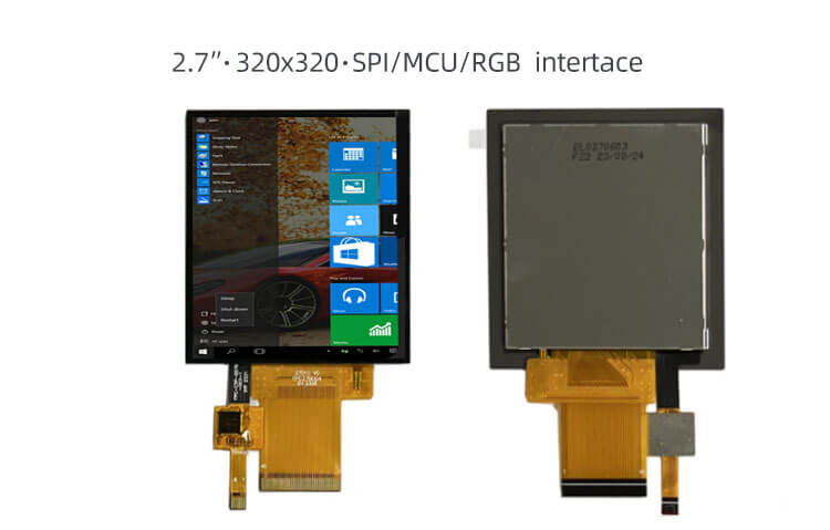
Page: 2.7 Inch Wide Temperature TFT LCD Display 320×320 with Capacitive Touch (ET027WQ20-KT).
Square panels are where catalogue shopping usually fails — most small TFT ranges are 4:3 or 16:9, and a 1:1 front panel is common on compact medical instruments. This one already carries the three interface options, so the "board speaks RGB, module speaks SPI" problem largely disappears at selection time instead of at integration time. What remains for semi-custom is the usual list: cover lens printing, brightness trim between 760 and 860 nits, FPC changes. Two things to check before designing it in: the 3.77 mm stack height includes the touch layer, so budget depth accordingly, and 760 nits costs backlight current — measure the runtime on your battery, not on the bench supply.
Youritech works in LCD display and touch screen R&D, design, customization, production and sales. The portfolio covers TFT LCD, OLED, touch panels, cover lenses and integrated display solutions, and healthcare projects can enter at any of those layers.
Display selection: LCD and OLED modules evaluated against size, resolution, brightness, viewing angle and interface requirements.
Touch integration: touch panel selection and integration matched to the equipment's user interface, including glove and enclosure evaluation.
Cover lens and bonding: cover lens dimensions, printing, surface treatment and bonding requirements reviewed as part of the assembly, not as separate parts.
Controller board solutions: panels combined with driver boards, OSD, cables and related electronics where the main board needs them.
Mechanical and connection design: FPC routing, connector position, module dimensions and installation constraints checked against the housing early.
Standard, semi-custom and full-custom routes are all available — see the Youritech Custom Display page and the LCD + Controller Solution. For the surrounding context, our guides cover what a healthcare display is, how to choose a medical display module, portable medical display requirements and medical imaging displays.
The final configuration depends on the application, the specifications and engineering evaluation. The module is a component; the equipment manufacturer remains responsible for validating the complete device and meeting the applicable regulatory requirements.
Developing a new medical device or replacing a display module? Send your screen specifications, drawings or existing module details through the contact page and we will come back with module options, drawings and honest notes on what is not worth customizing.
A display assembly developed or adapted for one equipment design. It can cover the LCD or OLED panel, touch sensor, cover lens, bonding, driver board, FPC and cables — one layer or the whole stack.
A standard module is used with its existing configuration. A custom module changes selected components or the overall design to meet mechanical, electrical or optical requirements the standard part does not meet.
Often, yes. Brightness, FPC, connector configuration, touch integration, cover lens and driver board are the common modifications. Feasibility depends on the specific module — some panels tolerate adjustment, some do not, and the answer comes from the module's design, not from its datasheet.
No. The module is a component inside the finished equipment. Device-level regulatory compliance is established by the equipment manufacturer on the complete, validated device.
No. It improves readability in bright or reflective conditions and stiffens the assembly, but it adds cost, complicates rework, and adds little for a panel read head-on in controlled lighting. Decide per project.
Screen size, resolution, interface, brightness target, touch requirements, mechanical dimensions, operating conditions and estimated quantity. A drawing or the part number of the display being replaced shortens the first review considerably.
Yes — prototype evaluation through to production, with quantities, lead times and long-term supply arrangements confirmed during the project review.


