Writer: Andrew MartinRelease Time: 2026-11-16 07:46Browse: 11
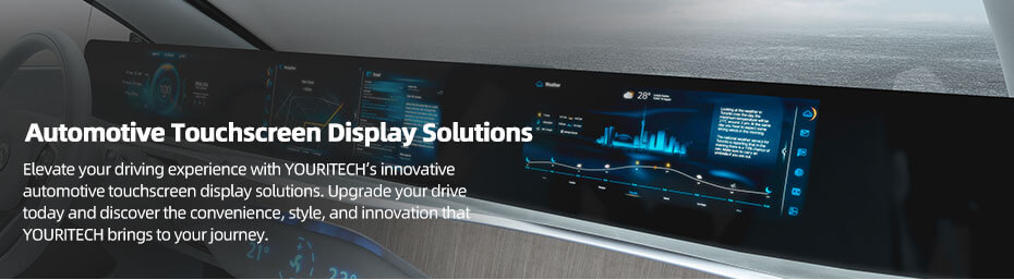
The cluster freezes first. Dashboard tooling is signed off, the CAN matrix is locked, and the display spec lands on someone's desk with a Friday deadline. The reflex is to open a catalogue, sort by size, tick the highest brightness, and move on. That is also how a project ends up with a 12.3-inch module that pulls 1.4 A at 12 V, a bezel that will not clear the steering column, and a touch controller nobody wrote a driver for.
This article goes in the other order: what each position in a vehicle actually demands from its screen, which five numbers decide whether a module can be used at all, what TFT and OLED really differ onFour positions once you are in a car, and six real modules from 5.0 to 15.6 inch with their numbers and their caveats. These are the decisions that separate a good automotive display application from a specification that gets renegotiated in month nine.
For the short version of the same decision, see How to Choose Automotive Display.
Contents

Four positions, four different sets of priorities — and four different kinds of automotive display application. Treating them as one category is where most specification mistakes start.
| Position | What it must do | What actually goes wrong | Normal size |
|---|---|---|---|
| Instrument cluster | Read at a glance, daylight and night, from one fixed eye position. No touch. | Reflections off the windscreen at midday; the panel is bright enough but the cover glass is not treated. | 7 to 12.3 inch, wide format |
| Centre infotainment | Touch, cover lens, bonding, and a UI that survives dashboard heat. | Thermal: sun load plus its own backlight pushes the panel past its operating range in a parked car. | 10 to 15.6 inch |
| Camera / mirror monitor | Whole-chain latency, high brightness, wide temperature at the glass. | Someone quotes the panel response time as the system latency. It is one link in five. | 4.3 to 7 inch |
| Passenger / auxiliary | Cost, power, viewing angle for an off-axis passenger. | A TN-mode panel bought to save money, then a passenger who cannot read it from the other seat. | 6 to 15.6 inch |
The driver looks at it for a fraction of a second at 500 to 700 mm. That distance sets everything: the smallest digit that stays legible, the contrast needed against the bezel, and the reason the panel should never be touch. A cluster with a 200 ms wake-up and a menu structure is a cluster fighting its own job.
Brightness matters, but not in the way the datasheet suggests. A cluster sits behind a cover glass, in a recess, often under a hood. The reflection off that glass at noon is what limits readability, not the panel's cd/m². This is why an anti-glare or anti-reflective treatment and a bonded stack can do more for a cluster than another 300 nits.
A dash-mounted display in a parked car in summer can see cabin air well above 70 °C, and the panel adds its own backlight heat on top. Wide-temperature ratings are the entry ticket, not the answer. Ask what the panel's own temperature rise is at full brightness, and where the driver board sits relative to that heat. A module rated to 85 °C still fails if the board behind it is rated to 70 °C.
Touch and cover lens belong to this position more than any other. In-cell touch removes a layer and a bonding step; a separate PCAP sensor plus cover glass gives you freedom in glass thickness and print, at the cost of two more interfaces to manage. Both are legitimate. Deciding late is what costs money.
Rear-view and mirror-replacement displays get blamed for latency that comes from the camera, the encoder, the harness and the SoC. A panel with a 30 ms response time does not make a 200 ms chain feel responsive. Specify the end-to-end budget first, then pick the panel that does not add to it.
The other trap: these displays sit where sunlight lands directly. 1000 nits behind untreated glass is worse than 700 nits behind a bonded, anti-reflective stack. Test the assembly, not the panel.
Rear-seat entertainment, climate panels, door-pillar displays, commercial-vehicle status screens. Off-axis viewing matters more here than absolute brightness, because the passenger is not sitting on the panel's normal. A 45/45/35/15 viewing angle is fine for a driver-facing cluster and unacceptable for a rear-seat screen. This is also the position where a 50% NTSC panel is the right answer, because nobody is grading photographs on it.
Everything else is negotiable. These five will stop a module from being usable at all.
The active area is the part that lights up. The viewing area is the clear aperture inside the bezel. The outline is the part you have to fit into the dashboard. A module can match your opening on paper and still put the bottom row of pixels behind the cover-glass print.
Take a 12.3-inch 1920 × 720 module: 292.032 × 109.512 mm of active area inside a 302.06 × 125.46 mm outline. That is roughly 10 mm of bezel left and right, and 16 mm top and bottom. If your CAD model came from the active area, the module will not fit. Build the mechanical model from the outline drawing, always.
1000 cd/m² on a datasheet means 1000 cd/m² at the centre, at a stated drive condition, with no cover glass, no bonding, no anti-glare film, at 25 °C. Put it behind 2 mm of printed glass and the assembly delivers less. Add a touch sensor and it drops again.
What you actually need to know: the target for the finished assembly, the transmission of your stack, and whether the backlight has headroom to compensate. A supplier who will not give you the panel's own transmission figure is telling you they have not done this before.
-30 to 85 °C is now common on industrial modules, and it is not the same claim as automotive-grade. It says the liquid crystal will not freeze or go isotropic across that range. It says nothing about vibration, thermal shock, humidity, EMI, or how the backlight behaves after 500 cycles.
If your programme needs automotive qualification, the test plan has to be agreed before samples: which standard, which severity, who runs it, and what a failure means. The panel-level environmental standards sit in ISO 16750, driver ICs are usually quoted against AEC-Q100, and camera-monitor systems have their own regulatory requirements on top. None of that comes free with a wide-temperature datasheet.
LVDS, MIPI DSI, parallel RGB, eDP. Matching the connector is the easy part. The harder questions: how many lanes, what pixel clock, which mapping, does the host output the resolution natively or scale, and is the backlight driver on the module or on your board.
Parallel RGB is cheap and simple and runs out of cable length fast. LVDS is the default from 7 inch up in embedded and automotive work. MIPI is what you use when the SoC only speaks MIPI and the module is small. Every one of those decisions has a cable and a connector behind it, and the connector is usually what fails first in a vibrating vehicle.
In-Cell touch means the sensor is inside the LCD cell: thinner, fewer layers, better optical clarity, but fixed at the factory. On-Cell and add-on PCAP keep the sensor separate, which lets you change glass thickness, print and surface treatment independently. Both work in vehicles; only one of them can be re-specified in month nine without a new panel.
If you are going to optically bond, decide that before the mechanical design is frozen. Bonding changes the stack height, the cover-glass tolerance, and the service strategy. It is not an upgrade you bolt on at the end.
IPS TFT LCD does most of the work in vehicles today, and the reason is boring: it is predictable. Wide temperature ranges, 1000 to 1600 nits with an LED backlight, 50,000 hours of backlight life, 16.7 M colours, and no image retention. When a cluster shows the same speedometer ring for eight years, predictable is the whole specification.
OLED earns its place where the design demands it. Self-emissive pixels mean black is off rather than grey, contrast is effectively unlimited, and the module can be thin or curved. In a premium centre display that mostly shows maps and media, that looks like a different class of product.
The costs are real. Static content at high brightness accelerates differential aging, which is exactly what a cluster or a fixed climate bar does. Peak brightness is limited by how hard you drive the emitters and how much heat you can remove. And the lifetime has to be judged on the actual UI, not a white-screen figure. If your interface is a fixed layout with a bright status bar, an LCD is the lower-risk answer and no amount of contrast will change that.
For very small readouts, PMOLED still makes sense: a 0.63-inch mono strip with an I²C interface costs less design effort than any LCD with a backlight. But that is a status line, not a cluster. If the requirement includes colour, graphics or touch, it is the wrong family of part.
Contrast ratio. Measured at the centre of the panel, at one temperature, on one sample. 1000:1 and 1500:1 are not visibly different in a car at noon; the ambient reflection is ten times either figure.
Response time. Tr + Td, usually grey-to-grey or black-to-white, measured at 25 °C. It gets worse cold. A panel quoted at 25 ms is not a 25 ms system, and at -30 °C it is not 25 ms either.
Colour gamut. 50% NTSC and 100% sRGB are not the same claim in different units, and neither tells you whether the reds look right. For a camera feed, 50% NTSC is acceptable. For a map with brand colours, it is not.
Viewing angle. 88/88/88/88 is a symmetry statement, not a guarantee that the image looks identical at 80 degrees off-axis. It means the contrast stays above 10:1 in all four directions. Whether the colour shift is acceptable is a different test, and yours.
Backlight life. 50,000 hours is usually quoted to half brightness at a specified current and 25 °C. Run it at 1600 nits in a hot dashboard and the number moves. Ask for the derating curve, not the headline.
"Free viewing angle." This appears on several wide-temperature modules and means the panel has no preferred viewing direction, usually an IPS-type LC mode without a quoted four-way number. Ask for the actual L/R/U/D figures before you design a mounting angle around it.
If you can fill those seven in, a supplier can quote in a day. If you cannot, the samples you order will be the wrong ones, and the second round is the expensive one.
Six modules, one per position and size class, all with public specifications. The point of the table is not to pick one — it is to show how differently the same set of numbers is balanced at each size.
| Part No. | Size | Resolution | Interface | Brightness | Outline (mm) | Temp / touch |
|---|---|---|---|---|---|---|
| A0500WVF2MAAA | 5.0" | 800 × 480 | RGB + SPI | 1000 | 121.3 × 78.8 × 6.1 | -30~85 / no |
| ET062BA06-TT | 6.2" | 480 × 1280 | MIPI | 1200 | 62 × 163 | -30~85 / in-cell |
| ET070WS07-KT | 7.0" | 1024 × 600 | LVDS | 1600 | 182 × 117.6 | -30~85 / no |
| ET103BA01-HL | 10.3" | 1280 × 480 | LVDS | 800 | 258.6 × 109.8 | -40~85 / no |
| ET123BA01-AP | 12.3" | 1920 × 720 | LVDS | 1200 | 302.06 × 125.46 | -30~85 / in-cell |
| ET156FH20-K | 15.6" | 1920 × 1080 | LVDS | 1300 | 363.8 × 215.9 × 9.3 | -30~85 / no |
This is the size class where a rear-view or mirror display lives, and the specification reads accordingly: nothing fancy, everything rated for a car.
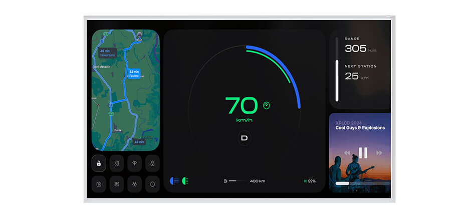
Where it stops being the right answer: any UI with text smaller than a few millimetres, any position where the panel is viewed at a steep angle by a passenger, and any design that expects the module to drive its own backlight. The 30 ms maximum response is a panel figure — if the camera chain adds 150 ms, this part will not rescue it.
480 × 1280 in a 62 × 163 mm outline is an unusual shape, and that is the point. It fits where a 16:9 panel cannot: a mirror stalk, a two-wheeler cluster, a door pillar, a charging-column readout.
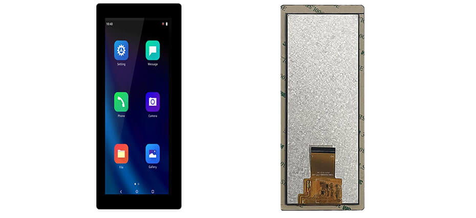
The catch is the 480-pixel width. That is roughly 26 characters of a 5 × 7 font per line at this size — fine for a speed, a gear, a battery bar and two icons, wrong for a menu tree. If the UI needs horizontal space, this part is the wrong shape and no amount of resolution will fix it.
1600 nits at 7 inch is not a normal number, and it changes what the module is for: commercial vehicles, off-highway machines, anything with a cab that has more glass than roof.
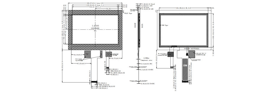
Two honest limits. 1024 × 600 on 7 inch is 170 ppi, so small type is coarse; that is fine for instrument work and not fine for a navigation map with street labels. And 1600 nits at this size means the backlight is doing real work — budget the current, and give the module somewhere for that heat to go.
1280 × 480 is 8:3 — the shape a dashboard actually has. This is the part you use when the information belongs in a horizontal strip rather than a rectangle.
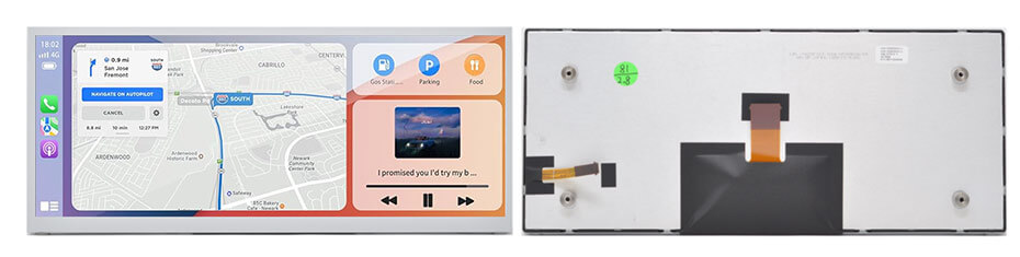
The 800 nit figure is the trade-off. You get a wide, cold-rated strip that sips power, and you accept that it is a shaded-dash panel. Put it behind a cover glass with a strong reflection and it will look dimmer than the number suggests. If the design needs sunlight readability at this size, the 12.3-inch class with 1200 nits is the honest alternative.
1920 × 720 at 12.3 inch is the resolution the industry settled on for a panoramic cockpit: wide enough for a cluster and a map side by side, short enough to sit behind a shallow dash.
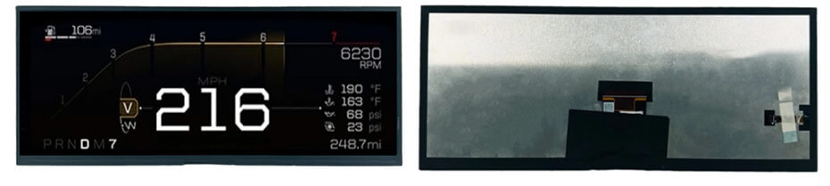
What it will not do: it will not give you a 16:9 image, it will not run a 4K UI, and it will not let you change the touch stack later. If the design needs a taller screen, this is the wrong aspect ratio and stretching a 16:9 UI across it will look wrong no matter how good the panel is.
Full HD at 15.6 inch, 1300 nits, 9.3 mm deep. This is a rear-seat screen, a large centre display, or a commercial-vehicle panel where the display is genuinely the product.
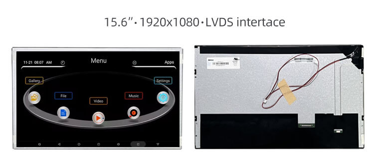
This is the module where "wide temperature" and "automotive grade" get confused most often. It is a wide-temperature industrial panel that is used in automotive and outdoor applications. If the programme needs qualification to a vehicle standard, that is a separate conversation with test reports, not a line on a datasheet.
There are more sizes on the shelf than the six above — the automotive range runs from 5 inch to 32 inch and beyond, including 8, 12.8, 17 and 19 inch panels. You can browse them in the automotive display selection.
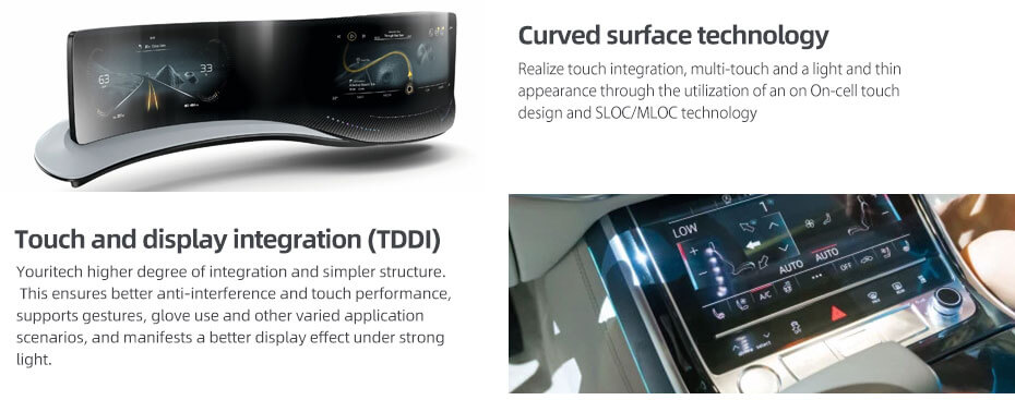
Youritech supplies LCD and OLED modules and the integration work around them Youritech supplies LCD and OLED modules and the integration work around them for automotive display applications: touch panels, cover lenses: touch panels, cover lenses, optical bonding, driver boards and cable assemblies. For automotive-related projects that usually means starting from a module in the table above and changing what the housing needs.
What is realistically adjustable: FPC length and connector position, backlight brightness and its driver, touch integration (add-on PCAP or an in-cell variant of the same panel), cover-glass shape, thickness, print and surface treatment, and the controller board. What is not adjustable: the glass itself, the pixel pitch, and the aspect ratio. A 1280 × 480 panel will not become 1920 × 720, and no amount of customization turns a TN panel into an IPS one.
For projects where the panel and the electronics have to be one assembly, the LCD + Controller Solution covers panels with AD boards, drivers, OSD and cables. For semi-custom and full-custom work — modified FPC, custom cover lens, bonded stacks — see custom LCD and OLED solutions, and the wider LCD display range for the standard catalogue.
Send the position in the vehicle, the size, the interface, the operating temperature and the mechanical envelope. If you have an existing part number, send it with the drawing — replacing a module that is going end-of-life is a different job from designing one in, and the second one is easier when we can see the original.
For a project discussion, contact Youritech. Equipment manufacturers remain responsible for validating the finished assembly and meeting the applicable vehicle regulations; a display module is a component, not a certified system.
In many automotive display applications, yes — but not because of the temperature rating.A -30 to 85 °C panel tells you the LC mixture survives that range. It does not tell you anything about vibration, thermal shock, humidity, EMI or long-term reliability. Whether it is acceptable depends on the vehicle programme's own test plan, and that plan has to be agreed before samples, not after.
AEC-Q100 applies to integrated circuits, so it is relevant to the driver ICs and the touch controller, not to the glass. Panel-level environmental testing is usually specified through ISO 16750 or the customer's own standard. Ask which documents exist for a given module rather than assuming a logo on the datasheet covers the assembly.
Because the diagonal is not a mechanical dimension. A 12.3-inch 1920 × 720 panel with in-cell touch can measure 302 × 125 mm, while a similar panel with a different touch stack and connector placement measures 310 × 128 mm or more. Always build the CAD model from the outline drawing of the exact part number you intend to buy.
In a shaded dash behind a bonded, anti-reflective cover glass, yes. Behind 2 mm of untreated glass with a glossy print, no. The panel number is not the assembly number, and the assembly is what the driver sees. If the design cannot control reflection, buy brightness.
Yes, by bonding a PCAP sensor and cover glass on top, which adds thickness, an interface and a bonding step. It is usually better to start from a variant that already has touch in the cell — the same panel family often exists both ways, for example a 12.3-inch 1920 × 720 with in-cell touch and a non-touch version at the same resolution.
LVDS from 7 inch upward, because it carries the pixel rate over a cable that survives a vehicle harness. Parallel RGB is workable on small panels with short flex runs. MIPI is the practical choice when the host is a mobile-class SoC and the module is compact and vertical. In every case, confirm lane count, pixel clock and connector mapping before layout.
Yes, as part of an integrated solution: panels with AD boards, LVDS or TTL driver boards, backlight drivers and cable assemblies. The exact configuration depends on the panel and the host interface, so it gets confirmed during the project review rather than assumed from a catalogue page.


