Writer: Andrew MartinRelease Time: 2026-11-13 05:41Browse: 7

Pick up a handheld ultrasound probe and the screen is roughly 30 cm from your face, tilted, with a window behind it. That single sentence rules out more display candidates than any datasheet column. Portable medical equipment does not shrink a desktop monitor; it puts a display into a device that has no space, no fan and no mains power.
This guide covers where these displays sit, what the enclosure and the battery actually demand, and which specifications are worth settling before you ask for samples. It is written for equipment designers, not for a parts catalogue.
Contents

Portable medical equipment is not one product category. It is four or five families that happen to run on batteries, and each one asks something different of the glass. The display follows from where the device is held and who reads it, not from a preferred size.
A handheld scanner is used at arm's length, in a darkened examination room, by someone whose other hand is holding a probe against a patient. The screen carries a live image, a measurement caliper and a small control strip, and it has to stay readable while the device moves.
This is the one portable category where resolution is genuinely the constraint. A 5-inch panel at 720×1280 gives roughly 294 ppi, which is enough to show a 1 mm structure without the image turning into blocks. Drop to 320×480 on the same diagonal and you are at about 165 ppi — fine for menus, poor for tissue.
Glucose meters, pulse oximeters, handheld ECG units, portable coagulation analysers. The screen shows a number, a unit, a status icon and occasionally a short waveform. Most of these devices are read in two seconds, at 25 to 40 cm, by a user who is not looking carefully.
Design effort belongs in numeral height and contrast, not in pixel count. A 2.8 to 3.5-inch panel at 320×480 with large type beats a 5-inch panel with a dense layout, and it leaves room in the enclosure for the battery and the sensor stack.
A transport monitor moves between ambulance, corridor and ward. It carries three to five parameters plus waveforms, runs on battery for the length of a transfer, and is read by people standing at different angles.
Here the binding constraint is usually power and thickness rather than image quality. A 1000 cd/m² panel that halves the runtime is a bad trade for a device with a defined transfer window.
Benchtop analysers that get carried to a ward, and portable instruments used in clinics. The screen mostly shows progress, a result table and a menu tree. A 5 to 7-inch panel with a clear grid and a responsive touch layer does the job; a high-resolution panel adds cost and heat for content that does not need it.
Not every portable device needs a screen with a UI. Insulin pens, patch pumps, sterilisation indicators and dental handpiece controllers often need a few characters or an icon. A small PMOLED or a monochrome segment display can be the right answer, and it draws almost nothing when most pixels are off.
A portable display is defined by what it cannot have: depth, cooling, a mains supply and a fixed viewing position. Those four limits decide the module long before image quality enters the conversation.
Front-panel area is shared with buttons, a probe connector, a battery door or a handle. Depth is worse: the module competes with the main board, the battery and the speaker. A 4.2 mm module and a 2.3 mm module look identical on a spec sheet and completely different inside a 26 mm housing.
Decide thickness together with the FPC exit direction. A module that meets the thickness target but exits its flex on the wrong edge forces a redesign of the housing, not a change of part number.
The same device is used in a dim examination room, a ward with a window, and occasionally outdoors. A display tuned for one of those is compromised in the other two.
Rough numbers that hold up in practice: 300–450 cd/m² is comfortable indoors; 700–800 cd/m² handles a bright ward or a device used near a window; 1000 cd/m² and above is daylight territory and comes with a power and backlight-life bill. Anti-glare or anti-reflective surface treatment matters as much as the figure — a glossy 500 cd/m² panel can be harder to read than a matte 350 cd/m² unit.
In a handheld device the display is usually the second-largest load after the processor, and on a device that spends most of its time showing a static image, it is often the largest. Backlight current scales roughly with brightness and area, so both choices are battery decisions.
Two honest options exist: accept lower brightness and design the workflow around it, or keep the brightness and increase the cell. Attempting both a 1000 cd/m² panel and a 10-hour runtime on a pocket-sized battery is where schedules slip.
Portable devices are usually sealed, often to IP54 or better, and have no fan. Backlight heat has nowhere to go, and the panel is sitting against the component that cannot exceed a touch-safe surface temperature.
High-brightness modules need a thermal path to the housing or a metal chassis. If the mechanical team has not been told the backlight power figure before the housing is tooled, this gets discovered as a hot spot on the front bezel.
Nobody holds a portable device square to their face. A tilt of 30–40° is normal, and the second reader is often standing beside the first. TN panels visibly wash out at that angle; IPS or a free-viewing-angle panel is the practical answer for anything held in the hand.
Five decisions cover most of the selection: size and pixel density, interface, mechanics, brightness, and temperature. Settle them in that order, because each one constrains the next.
Size sets the viewing area. Pixel density sets whether the content survives on it. For text and numerals, 165–200 ppi is plenty. For imaging — ultrasound, dermatoscopy, retinal images — 250 ppi and above is where detail stops being an approximation.
Resolution should match the native output of the processor. Upscaling a 720×1280 source onto a 480×800 panel does not add detail, and downscaling a UI designed for a larger panel costs you the numeral height you were trying to protect.
Match the module to your board. A bridge chip added late in the design brings a new power rail, a new failure mode and a new EMC question.
Connector pinout deserves the same attention as the interface name. Two modules labelled "40-pin MIPI" are not interchangeable; the pin order, the FPC contact side and the backlight connector differ between families.
Ask for the drawing before the sample. What matters: outline dimensions, active area position inside the outline, module thickness including the touch layer and the polariser, FPC length and exit edge, connector position, and mounting or frame features.
Confirm the active area offset too. A display that is 2 mm off-centre in its outline is a bezel problem that no firmware can fix.
Choose brightness from the worst lighting the device will meet, then check the power figure at that brightness rather than at typical. Backlight lifetime is quoted to half brightness — 20,000 to 50,000 hours is the usual band — and a device that runs its backlight at maximum all day will reach the low end of that range.
-20 to +70 °C covers most portable equipment. Check the cold end specifically: response time slows and brightness drops at -20 °C, and a device used in an unheated vehicle will meet that number. Storage range is normally wider and matters for shipping.
Also ask how long the module will be available. A portable device program runs five to seven years, and a panel that goes end-of-life in year three turns a good design into an unplanned redesign.
The table below is a starting point for a shortlist, not a specification. Real projects move a size or two in either direction once the housing is drawn.
For portable medical equipment, TFT LCD covers the large majority of projects. OLED wins in a narrower set of cases, and the deciding factor is usually operating pattern rather than image quality.
TFT LCD spans 0.5 to 15 inches with MIPI, RGB, SPI, LVDS and eDP options, brightness from 300 to 1000 cd/m² and above, and touch integrated as on-cell, in-cell or a bonded panel. Availability is the quiet advantage: industrial and medical TFT lines stay in production far longer than consumer parts.
For a device that runs a bright screen for eight hours, TFT LCD is the safe engineering choice, and the backlight is a known, quantifiable load.
OLED pixels emit their own light, so there is no backlight to power and no light leaking through a dark image. That gives deep black, high contrast and a thin module — useful on a status display that shows a few bright characters on black, and useful where the front panel has to stay slim.
Two questions to ask before choosing it for a medical device: how many hours a day will the screen run, and does the UI have static elements. Persistent brightness on fixed icons is where OLED image retention shows up first.
Not contrast ratio. Power at the brightness you need, module thickness, lifetime at your duty cycle, and how long the part will be available decide more portable projects than black level does. Test the candidate under your own UI and your own housing before committing — both technologies look good in a dark room on a test pattern.
On most portable devices the display is also the only input surface, so the touch layer and the cover lens are part of the display decision rather than a later add-on.
Capacitive on-cell or GFF touch is the common choice for a 3.5 to 7-inch device with a real menu structure. In-cell touch removes a layer and a bonding step, which buys thickness and often brightness; the trade-off is that the touch controller is tied to the panel, so a change of controller means a change of module.
Not every portable device should be touch. A meter operated with one thumb, a device used with nitrile gloves, and a device cleaned between every patient all argue for physical buttons. Gloved operation in particular is worth testing early: a projected-capacitive layer tuned for bare fingers may need a different controller setting or a thinner cover lens.
Cover glass is usually 0.7 mm or 1.1 mm. Thicker glass is more resistant to impact and worse for touch sensitivity and optical clarity. Air bonding is cheaper; optical bonding removes the internal reflection that makes a screen look milky under a window.
If the device is cleaned with alcohol wipes several times a day, say so at the quotation stage. Surface treatment, ink on the border and adhesive choice all change with the cleaning agent, and this is a specification that cannot be fixed after tooling.
Touch performance inside the finished housing is an electrical problem, not a panel problem. Grounding, the gap between the cover lens and the display, the length of the FPC and nearby switching supplies all shift the result. Build one complete unit and test it with gloves, with wet hands, and with the charger connected.
Two modules from our range bracket the portable category: a 5-inch panel for imaging devices that need pixel density, and a 3.5-inch panel for devices that need daylight readability. Both are modules, not finished monitors; suitability still depends on your layout, your electronics and your device-level validation.
Product page: 5 inch TFT LCD Display 720×1280 MIPI with In-Cell Touch
The interesting figure here is 294 ppi on a 5-inch diagonal. That is the density range where a handheld imaging device stops looking like a consumer gadget, and it comes with the touch sensor built into the panel rather than bonded on top.
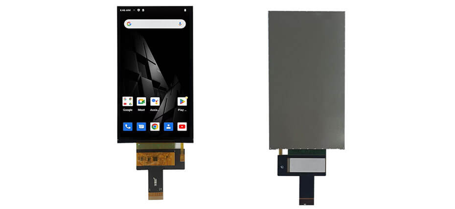
450 cd/m² is an indoor figure. It suits an examination room and struggles beside a window at midday, so if the device travels, plan a high-brightness variant or an anti-glare treatment rather than assuming the standard part will carry it. The narrow outline — 64 mm wide for a 5-inch panel — is the other reason this module gets shortlisted on handheld products.
Product page: 3.5 inch Wide Temperature TFT LCD 320×480 High Brightness with Capacitive Touch
This is the daylight-readable end of the range: 800 cd/m² with a capacitive touch panel on a 3.5-inch module, aimed at instruments used outdoors or in bright rooms. At 320×480 the picture is not an imaging surface, but for readings, waveforms and menus it is the right resolution for the size.
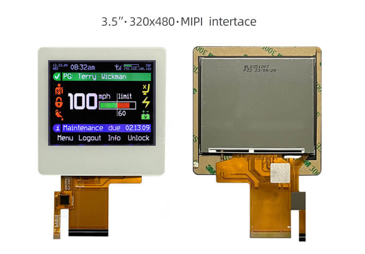
Two things to weigh before choosing it. The 4.24 mm thickness includes the touch stack, which is more depth than a bare 3.5-inch panel, and 800 cd/m² draws more backlight current than a 450 cd/m² module of the same size — on a battery device, that is a runtime conversation, not a free upgrade.
If your project needs something between these two, our TFT LCD module range covers 0.5 to 15 inches with the same selection logic applied.
Custom work usually starts where the standard part stops fitting: a taller FPC exit, a bonded cover lens with printed borders, an anti-glare treatment, a brightness level between catalogue steps, or a temperature range the standard module does not reach. Requirements we handle regularly:
One piece of advice from doing this repeatedly: lock the mechanical drawing and the interface before tooling the housing. A pinout change after the enclosure is cut is the most common avoidable cost in portable display projects.
Most portable display projects stall on missing information rather than on price. Ten lines of specification usually turn the first quotation round into a shortlist instead of a series of questions.
"Same as the current module, but 2 mm thinner and 800 cd/m²" is a workable brief. "A screen for a portable device" is not.
Test with your own interface before design freeze. Numeral size, image quality, touch behaviour with gloves and readability under real lighting cannot be judged from a datasheet, and they are also the four things hardest to change after tooling.
If the device also captures or displays diagnostic images, our guide to medical imaging displays covers resolution, grayscale and calibration requirements that sit outside general portable design. The broader healthcare display overview explains how the medical variants differ from standard industrial modules.
Working on a portable medical device? Send your specifications through our contact page and we will come back with module options, drawings and customization notes.
Most handheld devices sit between 2.4 and 5 inches, and transport monitors between 8 and 12.1 inches. The number is set by viewing distance and content, not by the category: a handheld ultrasound wants 5 inches or more for image detail, while a glucose meter is well served by 2.4 to 2.8 inches.
MIPI DSI is the usual choice for compact embedded processors, because it carries high bandwidth on few pins. RGB remains practical for simpler boards, and SPI suits small status displays where refresh rate does not matter. The right answer is the one your processor already outputs natively.
Around 300 to 450 cd/m² works for examination rooms and wards. Devices used near windows, in ambulances or outdoors generally need 700 to 1000 cd/m², with an anti-glare surface treatment. Every step up in brightness costs backlight power, which is a battery decision on a portable device.
For anything held in the hand, yes in practice. Portable devices are viewed at 30 to 40° of tilt and often shared between two people, and a TN panel washes out at those angles. IPS or a free-viewing-angle panel avoids that without changing the rest of the design.
Only if the user interface needs one. Meters, pumps and devices operated with gloves often work better with physical buttons, while analyzers and handheld imaging devices usually need touch. If touch is in scope, test it with gloves, with wet hands and with the charger connected.
Yes, provided it meets the technical requirements of the device. What a module cannot do is establish compliance on its own: the finished product is evaluated as a complete medical device, and display-related requirements are assessed at system level. We supply modules and their specifications; device validation stays with the equipment manufacturer.
Yes. Size, resolution, interface, brightness, touch integration, cover lens, FPC layout and temperature range can all be adjusted, and non-standard aspect ratios are possible. Standard and semi-custom options usually shorten the schedule, so it is worth checking those first.


